
Fan filter unit fan B3P400-EC102-095
B3P400-EC102-095 is an AFL fan filter unit fan in the published model records. Review its documented specifications, installation requirements and source information against your equipment duty.
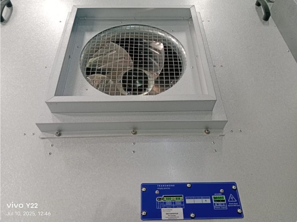
Review the documented model data
FFU format: 4 × 4. The FFU presentation lists this configuration for a 4 × 4 unit. Match the suffix, shaft and controller before requesting a sample.
Check the installation and operating point
Check the FFU format, assembly envelope and fixing arrangement against the equipment drawing. Define the operating point with the intended filter resistance and verify controller and feedback requirements.
Match the electrical interface
Confirm the supply and the exact speed-control and feedback interface required by the equipment controller. An EC designation alone does not establish the supported control signal.
Use the technical documents
Check the attached model documents and their page references before sample evaluation. Confirm the complete suffix and document revision. Performance at your required duty point must be checked on the corresponding curve.
Discuss this model
Include B3P400-EC102-095, required airflow and static pressure, power supply and available installation space in your inquiry. Attach the equipment layout and identify any required control or feedback signals.
EC fans and blowers · FFU fans
Specifications
- Model
- B3P400-EC102-095
- Drive
- EC
- FFU format
- 4 × 4
- Presentation configuration
- B426
- Presentation drive
- Integrated 485 drive
Selection from the source sheet
The FFU presentation lists this configuration for a 4 × 4 unit. Match the suffix, shaft and controller before requesting a sample.
Related documents and engineering decisions
FFU, data centre and AHU engineering presentation · p. 5Equipment fit and selection
Specify filter pressure drop, airflow per unit, Hall feedback and the controller used for the approved FFU assembly.
Equipment selection guide What to check before ordering Factory and qualification documentsRelated models to review
Compare the complete suffix, mounting and operating conditions before specifying a replacement.
4 × 4 FFU assembly · AFL equipment presentation, slide 5.B3P400-EC102-048B3P400-EC102-048: review fan filter unit fan specifications, mounting requirements and technical sources before selecting a fan for your equipment.4 × 4 FFU assembly · AFL equipment presentation, slide 5.B3P400-EC102-065B3P400-EC102-065: review fan filter unit fan specifications, mounting requirements and technical sources before selecting a fan for your equipment.4 × 4 FFU assembly · AFL equipment presentation, slide 5.B3P400-EC102-067B3P400-EC102-067: review fan filter unit fan specifications, mounting requirements and technical sources before selecting a fan for your equipment.Related resources and guides
 FFU, data centre and AHU engineering presentation · source previewTechnical resourcesFFU, data centre and AHU engineering presentationApplication-specific models, paired duty points, controller configurations and equipment-level test examples.
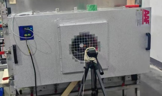 2 × 4 fan filter unit · AFL equipment presentation, slide 4.ApplicationsCleanroom fan filter units (FFUs)Choose the FFU size, controller and fan together. Compare airflow at filter pressure drop and confirm the shaft and feedback configuration.