
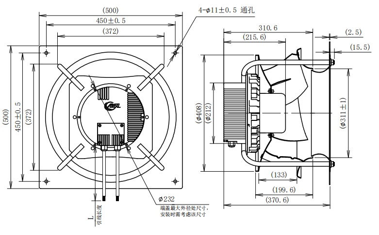
When an AHU fan runs at its maximum permitted speed, the next purchase decision depends on what the system is actually delivering. Record the required and measured airflow, the pressure measurement location and the operating condition. Then check the exact fan configuration against its selection curve. AFL’s B3P456 presentation provides a useful example of why a duty-point figure and a model name need to be checked together before a replacement or approval decision.
What does the manufacturer’s example actually establish?
Nuaire’s AIRE-VOLVE Single brochure describes a constant-pressure extract arrangement in which opening and closing dampers changes system pressure and the fan adjusts speed. If the system exceeds the maximum or minimum limits, the fan stays at the limiting speed. The same specification assigns commissioning to a qualified engineer and calls for adjustment to achieve the required ventilation rates using a measuring device. See PDF page 8, printed pages 14–15.
This is a documented Nuaire arrangement. For an AFL fan proposal, request the selected fan’s curve and interface documents, plus the system controller’s operating description. The equipment integrator must establish how those components work together.
How does the AFL B3P456 example change the selection review?
AFL’s equipment-selection presentation, slide 24, names B3P456-EC137-950 and lists two headline duties: 5,000 m³/h at 900 Pa and 4,000 m³/h at 1,000 Pa. These are two paired operating conditions. A requirement for 5,000 m³/h at 1,000 Pa creates a third selection question that must be checked on the appropriate curve.
The slide also contains a document discrepancy worth resolving: its detailed new-design table and curve legend identify -951, while the headline identifies -950. Request the current curve and drawing for the exact suffix being quoted. The table’s power, speed and efficiency values should stay with the configuration identified in that table. This is a practical reason to put the full suffix and document revision on the RFQ.
What can those two points support?
They let the buyer describe two candidate duties for review. If the equipment needs constant airflow as resistance changes, ask the supplier to show that required airflow at each resistance on the confirmed model curve. The two headline points alone do not establish a constant-airflow control range.
What decision can follow the curve review?
If the supplier confirms the required duties within the documented operating limits, retain the proposed fan for installed testing. If the confirmed curve cannot support a required duty, ask for another configuration or a design review of the air path. Evaluate the replacement against the mounting envelope, power supply, controller interface and project acoustic requirements before ordering.
Which demand scenarios belong in the acceptance plan?
Use the agreed room-demand schedule to identify the combinations that the installed system must serve. Write the damper positions, pressure setpoint and sensing location beside each scenario. Include the filter condition and any other resistance assumptions used in selection. This gives the commissioning team a repeatable test condition.
High demand
Ask the designer which simultaneous room demands define the design case. During that test, record the requested control output, actual fan speed if available, sensed pressure and measured terminal flows. If the fan reaches its upper limit, retain those readings and ask the designer to assess the specific unmet duty before changing the setting.
Minimum demand
Agree which rooms still require background ventilation and which dampers may close. Repeat the pressure and terminal-flow measurements at that state. Ask the controls supplier to identify the allowed minimum-speed setting and the intended response when the measured pressure cannot be held there.
Which readings help decide whether to change the fan?
Start with a shared measurement record. A controller can report a percentage command while the engineer needs the actual operating condition. Identify what each available signal represents and where pressure and flow were measured. Compare the observations with the design state before interpreting the result.
Pressure is close to the setpoint, but one terminal has low flow
Review the affected branch, damper state and measurement with the system designer. The pressure sensor’s location matters to that interpretation. Obtain the terminal results under the same combined demand condition before choosing a larger fan.
The pressure target is missed at maximum permitted speed
Check the complete demand state, filter condition, air-path restrictions, rotation or installation requirements, and whether the feedback confirms the intended speed. These checks can identify a mismatch between the selected and installed conditions. Ask the engineer to relate the observed operating point to the confirmed fan curve.
The smallest demand state also fails acceptance
Review minimum ventilation requirements, the allowed minimum setting and the controller’s response together. A larger fan chosen for peak duty still needs a workable low-demand condition. Include both ends of the operating range in the selection review.
How can a buyer distinguish a control limit from an accepted result?
A limit indication describes the control state. The acceptance record must also show whether the scheduled terminal flows and other project criteria were achieved. Ask the engineer to record pass or fail against the agreed criteria for each test condition. If a criterion is missed, identify who will review duct resistance, damper settings, sensing arrangements and the selected fan duty. These are investigation items; the readings alone may not establish the cause.
Hypothetical example: an extract system serves several rooms, and the design requires a particular group to operate in boost together. If that combination brings the fan to its maximum setting, the buyer should request the measured flow for each required terminal and the corresponding pressure reading. A successful test of one room in isolation cannot establish the result for that combined condition.
What should engineering and purchasing sign before sample or system acceptance?
Prepare one test sheet with the equipment revision, fan and controller identifiers, damper-state schedule, pressure measurement location, required terminal flows, recorded results and approving engineer. Ask the supplier to attach the relevant selection curve and control description. Record the approved minimum and maximum settings and who may change them.
For a fan inquiry, send the selected demand scenarios and the associated airflow and pressure requirements to AFL. Identify the party responsible for pressure control and site commissioning. This makes the fan quotation’s scope and the integrator’s acceptance work explicit.
For an AFL technical inquiry, attach the complete B3P suffix, the supplier’s current curve revision, required flow/pressure pairs for each scenario, equipment section drawing and actual control-interface requirements. Ask for a written selection response that identifies supported points and unresolved conditions. The system engineer can then turn that response into an installation and commissioning plan.
| Source detail | What to carry into the RFQ | Open item |
|---|---|---|
| Headline model | B3P456-EC137-950 | Confirm the exact offered build |
| Headline duty 1 | 5,000 m³/h at 900 Pa | Confirm curve and test configuration |
| Headline duty 2 | 4,000 m³/h at 1,000 Pa | Check every required equipment duty |
| Detailed table / curve label | B3P456-EC137-951 | Resolve suffix difference before using detailed values |
Buyer FAQ
Does a pressure setpoint prove that every room receives its scheduled airflow?
The acceptance plan should include terminal measurements for the agreed operating scenarios. Record the pressure reading alongside them so the engineer can relate the controller’s measurement to the rooms being served. The sensing location and system arrangement determine how that reading should be interpreted.
Should procurement specify the lowest possible minimum speed?
Ask the designer to define the required background duty, then obtain the fan and controller suppliers’ permitted operating limits. Have the commissioning engineer document the setting that meets that duty. A numerical minimum without its operating condition leaves the acceptance requirement incomplete.
Can the commissioning team raise the maximum setting after a failed test?
Require the responsible engineer to review the proposed change against the selected fan’s limits and the equipment requirements first. Record the revised setting and repeat the affected acceptance tests. Include any project noise or electrical criteria in that review.
Who decides where pressure is measured?
Assign the sensing arrangement to the responsible system designer or controls engineer and have it shown on the approved drawing. The test sheet should identify the actual measurement point so subsequent tests can reproduce the condition.
Does an EC fan designation confirm this constant-pressure behaviour?
Request the exact controller description and fan interface details. The Nuaire example describes a particular integrated arrangement. Confirm the behaviour and responsibility for the proposed AFL installation with the equipment integrator before accepting the specification.
Does the slide prove that -950 and -951 are interchangeable?
The slide identifies different suffixes in its headline and detailed data. Request separate confirmation of the offered build, performance curve and outline. Treat the discrepancy as an open selection item until the supplier resolves it in writing; retain that response with the sample order.
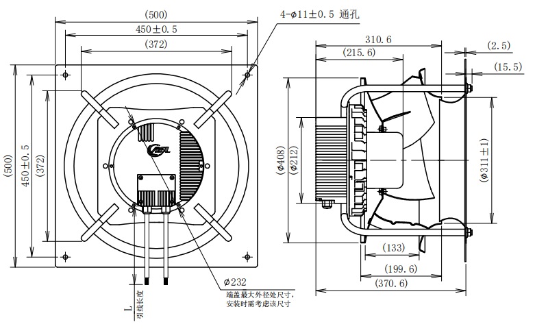 B456 installation drawing · AFL equipment presentation, slide 24.B3P456-EC137-950